Arduino LDR-Based Automatic Light Control System
Overview
Introduction
In the field of electronics and embedded systems, automation plays a vital role in improving efficiency, reducing human effort, and conserving energy. One of the simplest and most practical examples of automation is an automatic light control system. This project demonstrates how environmental conditions can be used to control electronic devices intelligently.The system is built using the Arduino Uno and an LDR (Light Dependent Resistor), which acts as a light-sensing component. The LDR detects the intensity of light in the surroundings and converts it into a varying electrical signal. This signal is then processed by the Arduino, which makes decisions based on predefined conditions.
When the surrounding light intensity falls below a certain threshold, indicating darkness, the system automatically turns ON an LED. Similarly, when sufficient light is detected, the LED is turned OFF. This eliminates the need for manual switching and ensures efficient use of electrical energy. Overall, this project provides a clear understanding of sensor-based automation, analog input processing, and real-time decision-making, making it an ideal starting point for students learning embedded systems and smart electronics.Components Required
The following components are required to build the Automatic Light Control System using Arduino and LDR:
- Arduino Uno
It acts as the main controller of the system. It reads the input from the LDR and controls the output (LED or light source). - LDR (Light Dependent Resistor)
It is used to detect the intensity of light. Its resistance changes according to the amount of light falling on it. - 10kΩ Resistor
It is used along with the LDR to form a voltage divider circuit, which helps in generating a measurable voltage for the Arduino. - LED (Light Emitting Diode)
It is used as an output device to indicate whether the light is ON or OFF. - 220Ω Resistor
It is connected with the LED to limit the current and protect it from damage. - Breadboard
It is used to assemble the circuit without soldering. - Jumper Wires
These are used to connect different components in the circuit.
Circuit Connection
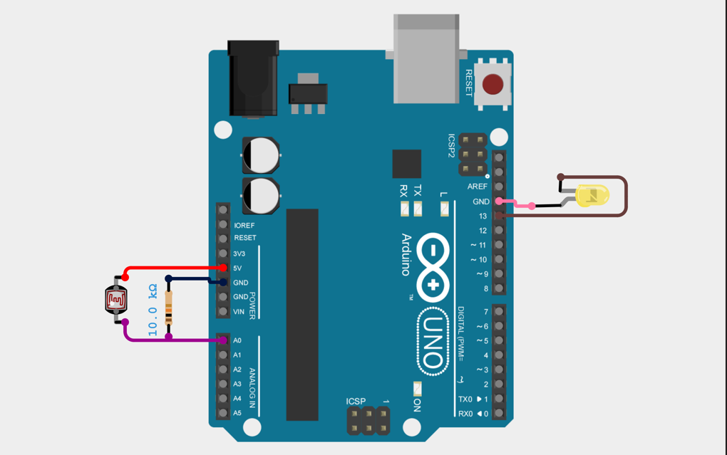
The circuit is based on a voltage divider principle using LDR and a resistor. The detailed connections are as follows:
1. LDR Connection
- One terminal of the LDR is connected to 5V of Arduino.
- The other terminal of the LDR is connected to Analog Pin A0 of Arduino.
2. Resistor Connection (Voltage Divider)
- One end of the 10kΩ resistor is connected to A0 (same point as LDR).
- The other end of the resistor is connected to GND.
This combination forms a voltage divider circuit, allowing Arduino to read varying voltage levels based on light intensity.
3. LED Connection
- The positive terminal (long leg) of the LED is connected to Digital Pin 13 through a 220Ω resistor.
- The negative terminal (short leg) of the LED is connected to GND.
4. Power Supply Connection
- Arduino is powered through USB or an external 5V supply.
- The 5V and GND pins are distributed to the breadboard for circuit operation.
Summary of Connections
- LDR → 5V and A0
- 10kΩ Resistor → A0 to GND
- LED → D13 to GND (via 220Ω resistor)
Arduino Code Explanation (LDR Light Control System)
This Arduino program is designed to control an LED automatically based on the surrounding light intensity using an LDR (Light Dependent Resistor).
The Arduino continuously reads the light level and decides whether to turn the LED ON or OFF.1. Variable Declaration
int ledPin = 13;
int threshold = 500;
ldrPin = A0
This defines that the LDR sensor is connected to Analog Pin A0 of the Arduino Uno.ledPin = 13
This defines that the LED is connected to Digital Pin 13.threshold = 500
This is a reference value used to decide whether it is dark or bright.
2. Setup Function
pinMode(ledPin, OUTPUT);
}
- The
setup()function runs only once when the Arduino starts. pinMode(ledPin, OUTPUT)sets pin 13 as an output pin, so it can control the LED.
3. Loop Function
int ldrValue = analogRead(ldrPin);
- The
loop()function runs continuously. analogRead(ldrPin)reads the value from the LDR.- The value ranges from 0 to 1023, depending on light intensity.
=> This value is stored in the variable ldrValue.
4. Decision Making (if-else condition)
digitalWrite(ledPin, HIGH); // ON
} else {
digitalWrite(ledPin, LOW); // OFF
}
}
This is the main logic of the program:
- If
ldrValue < 500
→ It means the environment is dark
→digitalWrite(ledPin, HIGH)turns the LED ON - Else (when value is greater than 500)
→ It means the environment is bright
→digitalWrite(ledPin, LOW)turns the LED OFF
5. How the Code Works Together
- The LDR senses light
- Arduino reads the value using
analogRead() - It compares the value with the threshold
- Based on the result:
- Dark → LED ON
- Bright → LED OFF
- This process repeats continuously in the loop
6. Important Concept for Students
=>This program follows a simple logic:Input → Processing → Output
- Input: LDR sensor (light detection)
- Processing: Arduino (decision making using if-else)
- Output: LED (ON/OFF control)
7. Key Notes
- The threshold value (500) may need adjustment depending on the environment
- Different lighting conditions will produce different readings
- The loop runs very fast, so the system responds instantly

Purpose
The main purpose of the Automatic Light Control System using Arduino and LDR is to automatically control a light source (such as an LED or bulb) based on the surrounding light intensity. In this system, an LDR (Light Dependent Resistor) is used to sense the ambient light level. The resistance of the LDR changes according to the intensity of light falling on it. The Arduino reads this changing value through its analog input and compares it with a predefined threshold value. When the surrounding environment becomes dark, the system automatically turns the light ON. When sufficient light is present, the system turns the light OFF. This eliminates the need for manual switching and provides an energy-efficient automation solution. This project is commonly used in the following applications:- Street lighting systems
- Garden and outdoor lighting
- Smart home automation
- Security lighting systems
- Energy-saving lighting solutions
Advantages
- Energy Efficient
The system turns ON the light only when required, which helps in saving electricity. - Automatic Operation
No manual intervention is needed, making the system fully automatic. - Low Cost
The components used are inexpensive and easily available. - Simple Design
The circuit and programming are simple, making it suitable for beginners. - Wide Range of Applications
It can be implemented in homes, streets, industries, and public places.
Disadvantages
- Affected by External Light Sources
Sudden light sources like vehicle headlights may cause incorrect switching. - Threshold Dependency
The system performance depends on proper threshold setting. Incorrect values can lead to malfunction. - Limited Intelligence
The system only responds to light intensity and does not consider other factors like motion or time. - Environmental Impact
Dust, shadows, or weather conditions can affect the accuracy of LDR readings.
Administrator
Frequently Asked Questions
Common questions about Arduino LDR-Based Automatic Light Control System. Find answers to the most frequently asked questions.
User Reviews & Comments
Share your experience with this IoT Blog. Your feedback helps our community make informed decisions!
Share Your Experience
Help others by sharing your thoughts about this IoT Blog.
Related Blogs
Explore more IoT Blogs in the same category
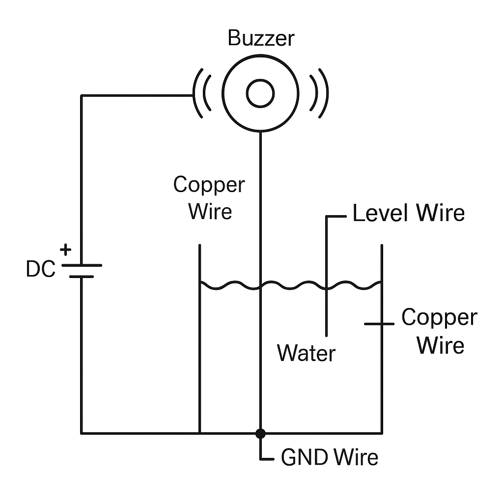
DIY Water Tank Full Alarm Using Copper Wire | No Arduino, No Sensor – Low Cost Project
Homemade Projects
Learn how to make a DIY water tank full alarm using copper wire without Arduino or any sensor. This low-cost homemade water level indicator project helps you prevent tank overflow with a simple circuit using just a buzzer and copper wires.
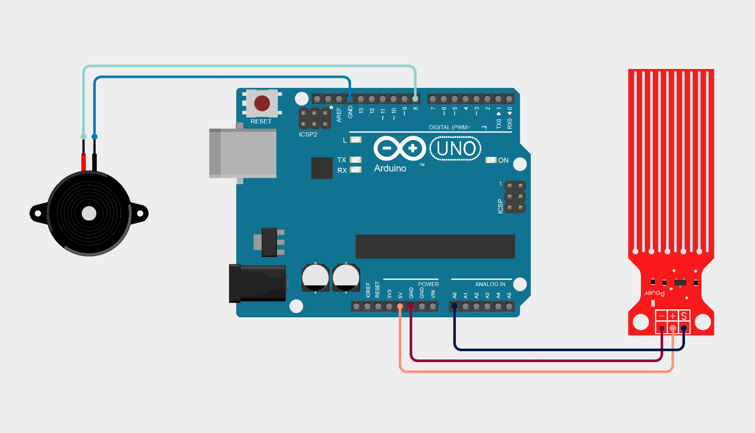
Arduino Water Leak Detection System using Water Sensor and Buzzer
Homemade Projects
This project demonstrates a simple Arduino-based Water Leak Detection System using a water sensor module and a buzzer. The system continuously monitors moisture levels through the sensor and sends analog data to the Arduino Uno.

Ultrasonic Distance Measurement Project Using Arduino
Homemade Projects
Ultrasonic distance measurement using Arduino and the HC-SR04 sensor to detect how far an object is from the sensor. This project demonstrates real-time distance calculation using sound waves and Arduino programming.
No Reviews Yet
Be the first to share your experience with this IoT Blog!