AT24C02 EEPROM Explained: Features, Pinout, Interfacing & Use Cases for IoT Projects
Overview
What is AT24C02 EEPROM?
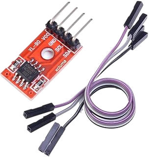
The AT24C02 is a 2-Kilobit (256 x 8) serial Electrically Erasable Programmable Read-Only Memory (EEPROM) developed by Microchip Technology. It uses the I2C (Inter-Integrated Circuit) protocol for communication, allowing easy interfacing with microcontrollers and digital devices. Designed for non-volatile memory storage, it retains data even after power is removed.
This makes it a go-to solution for storing configuration data, calibration settings, and temporary logs in embedded systems.Key Features of AT24C02
-
Memory Size: 2Kb (256 bytes total; organized as 32 pages of 8 bytes)
-
Interface: I²C (2-wire)
-
Operating Voltage: 1.7V to 5.5V (compatible with both 3.3V and 5V logic)
-
Low Power Consumption: 1 µA standby current
-
Write Time: Typical 5ms
-
Write Protection: Hardware-based write protection via WP pin
-
Data Retention: 100 years
-
Endurance: 1,000,000 write/erase cycles
-
Package Types: 8-lead SOIC, DIP, TSSOP, UDFN
AT24C02 Pinout Description
| Pin Number | Pin Name | Description |
|---|---|---|
| 1 | A0 | Address input |
| 2 | A1 | Address input |
| 3 | A2 | Address input |
| 4 | GND | Ground |
| 5 | SDA | Serial Data (I²C data line) |
| 6 | SCL | Serial Clock (I²C clock line) |
| 7 | WP | Write Protect (active high) |
| 8 | VCC | Power Supply (1.7V to 5.5V) |
How AT24C02 Works
AT24C02 operates on the master-slave communication model. When connected to a microcontroller, the EEPROM acts as a slave device. The microcontroller sends the memory address and either writes data to it or reads data from it over the I2C protocol. The EEPROM handles internal memory management automatically.
Each write operation is internally acknowledged by the EEPROM and can take up to 5ms to complete.Package Types of AT24C02
-
AT24C02N – DIP-8 package (through-hole, breadboard-friendly)
-
AT24C02C – SOIC-8 package (surface mount)
-
AT24C02B – Automotive grade
-
AT24C02D – Industrial-grade temperature and voltage support
-
AT24C02-MAHM – 8-lead UDFN for ultra-compact devices
Interfacing AT24C02 with Microcontrollers
To interface AT24C02 with a microcontroller:- Connect SDA and SCL lines to the respective I2C pins on the microcontroller
- Pull-up resistors (typically 4.7kΩ to 10kΩ) are required on SDA and SCL lines
- Connect VCC and GND to power and ground
- If not using write protection, tie the WP pin to GND
Important Note: Always monitor I²C address collisions when using multiple I2C devices on the same bus.
Advantages of Using AT24C02
- Reliable non-volatile memory
- Simple I2C interface for easy programming
- Low power and small form factor
- Cost-effective for small data storage needs
- Supports multiple devices on the same bus via address pins
Example: Writing and Reading Data from AT24C02 (Pseudo Code)
#define EEPROM_ADDRESS 0x50 // Base address
i2c_start();
i2c_write(EEPROM_ADDRESS << 1); // Write mode
i2c_write(0x00); // Memory location
i2c_write(0x55); // Data
i2c_stop();
i2c_start();
i2c_write(EEPROM_ADDRESS << 1);
i2c_write(0x00); // Memory location
i2c_start();
i2c_write((EEPROM_ADDRESS << 1) | 1); // Read mode
byte data = i2c_read_nack();
i2c_stop();
Common Use Cases
Although not strictly limited to IoT, AT24C02 is frequently used in:- Consumer electronics configuration storage
- Embedded system calibration data
- Industrial automation logs
- Smart cards and ID systems
- Automotive electronics
- RTC modules (for date/time storage)
- Peripheral device firmware identification
Things to Keep in Mind
- Always ensure power is stable during write operations to avoid data corruption
- Do not exceed 1 million write cycles for a specific byte
- Observe correct I2C bus timing and voltage levels
- Implement write delay handling in your firmware for proper memory timing
Where to Buy
Prices may vary. Click on "Buy Now" to check current availability and pricing.
Administrator
Frequently Asked Questions
Common questions about AT24C02 EEPROM Explained: Features, Pinout, Interfacing & Use Cases for IoT Projects. Find answers to the most frequently asked questions.
User Reviews & Comments
Share your experience with this IoT Blog. Your feedback helps our community make informed decisions!
Share Your Experience
Help others by sharing your thoughts about this IoT Blog.
Related Blogs
Explore more IoT Blogs in the same category
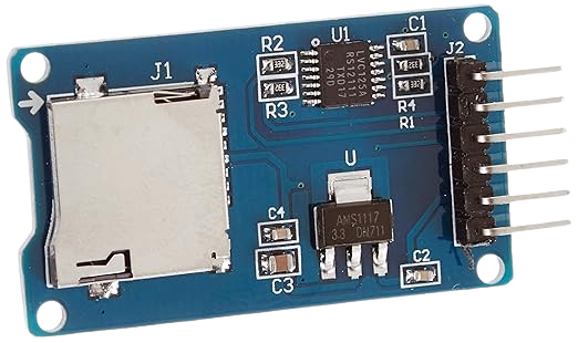
Best SD Card Module for Data Logging in Electronics Projects – Full Guide, Uses, and Setup
Storage Modules
Discover everything about SD Card Modules for efficient data storage in electronics projects. Learn how they work, top features, wiring setup, and best use cases for reliable data logging. This complete guide helps you choose the right module and integrate it easily for accurate performance tracking in any embedded system or automation setup.
No Reviews Yet
Be the first to share your experience with this IoT Blog!